


PRECISION MANUFACTURING
FAQs
Cambridge Technology Product Brand
Depending upon how the supply is configured or the distance between the supplies and the driver boards, the S + may have to be connected to the Out + either right at the supply or at the driver board and the S – may have to be connected directly to the Out – either right at the supply or at the driver board. The ground connection between the Out – and Out + and the ground connection between the two servo drivers should be a very heavy gauge low resistance wire. The power supply ground connection is optional and is usually not connected
For just a single CRS set, we recommend a power supply with 12 V and 1 A. The CRS operates at only one frequency, it is very efficient and doesn’t require a lot of power.
Ensure that there is continuity on the status channels of the data cable. Check the results for parity errors. If there are parity errors, this indicates that either your controller is expecting the incorrect parity or there is a break in the connection. Check the format of the status signal as described in the chapter detailing the XY2 100 protocol. If none of these solutions correct the problem, contact us for technical support.
First, ensure that there is no obstruction to the mirrors. Once you have determined that the mirrors can move, check that the proper power connections have been made, and that the power has been applied. Next, check that all other connections have been made correctly, including the connection to the motor. If the system still will not power up, contact us for technical support.
Ensure that the system is on, and that the controlling device is delivering the appropriate signals. Check the continuity of the command cable, and that the connections to the controller are firm. If the system will still not react to commands, contact us for technical support.
In certain demanding applications, a significant amount of power is consumed in the motor that generates significant heat in the motor coil. This heat can propagate through the motor body and rotor, change the motor parameters as well as the encoder response, and compromise the system’s accuracy. To address this potential problem, we have developed active cooling solutions to regulate the motor’s temperature.
Thanks to the accurate representation of the scanner system by the state space model, LightningTM II can drive a wide range of loads. The algorithm can model up to four resonance frequencies, enabling it to control loads that would be impossible to drive with any available servo electronics. In order to configure a system with a custom load, contact us for technical support.
Lightning II systems incorporate six* differentiating elements:
Encoder Position Detector – Advanced encoder technology and state-of-the-art galvo motor design provide ultra-high resolution and ultra-low drift, resulting in unsurpassed
PWM Drive Output – Extremely efficient power transfer from the driver to the motor enables unmatched speed and accuracy even with very large
Observer-based State-space Modeling – The control algorithms in the servo driver are tailored to a specific motor / mirror combination, which enables the servo to achieve maximum performance in speed and
GSB Communication Protocol – The General Scanning Bus, a new bi-directional high speed serial communication protocol between controller and servo driver(s), delivers sophisticated control to the scanners, and status and streaming probe data to the
ScanMaster Control Software – Utilizing a single USB connection between a computer and the scanning system, this revolutionary control software provides automation and optimization far better than any other
TuneMaster II Setup Software – Automated and user-friendly tools help shorten optimized tune development, automate production tuning and improve
The LED on the LightningTM II digital servo driver is currently* used as a general diagnostic indicator. During normal operation the LED remains constantly illuminated when the driver is idle, and flickers when the servo is issuing commands. If the LED is not illuminated at all, this indicates a problem, and you may experience problems with communication. Verify the power to the board is connected correctly (connector pins and voltage levels). If the power connection is correct, contact Cambridge Technology for technical support.
It depends on the mirror inertia, angle, and command waveform.
Laser Quantum Product Brand
Yes, our green pump sources such as the finesse or opus are well suited to pump also Ti:S lasers running in ps mode or as cw laser. Existing customers are successfully applying Laser Quantum lasers in these areas.
Using measurements the thermal resistance of the forced air cooling plate was calculated to be 0.08C/W. This means at normal laboratory temperatures and conditions, the temperature of the 6W opus 532 can be maintained
There are different causes which can prevent the system from lasing. Please check the following steps to ensure that this is not caused by an external factor.
Please switch the system off completely (including power supply unit), wait for approximately 30min and restart the system.
Please ensure that the cooling system is running properly:
Are the tubes connected?
Is the chiller switched on?
Is the fluid circulating?
What are the temperatures of the laser head and power supply unit and are the temperatures settling?)
Please ensure that all cables and the interlock connector are secured properly at the laser head and/or at the power supply unit.
Please ensure that the key is turned to the ‘on’ position, enabled and that the warm up phase is finished.
Check and ensure that the pump diode drive current is set to a value above lasing threshold, e.g. use a value in the between 50% – 100%
If the problem still occurs please contact our Laser Quantum Support Team.
There are different causes which can lead to a performance change of the laser system. Please check the following steps to ensure that the performance change is not caused by an external factor.
Please ensure that you measured the output power correctly, (see item 5 above).
Please switch the system off completely (including power supply unit), wait for approximately 30min and restart the system.
Please ensure that the cooling system is adequate and working properly, (see item 3 & 4 above).
Please ensure that all cables are secured properly at the laser head and at the power supply unit.
Please ensure that the laser head is mounted on a flat and clean metallic surface with no more than a torque of 2Nm. If the base, where the laser head is mounted on, is slightly bent or if there is some debris between the laser head and the base or if the laser head is mounted with uneven torque on screws leading to a bending of the laser housing, this could affect performance.
Please ensure that there are no back reflections of laser light being redirected into the laser aperture.
If a fibre delivery system is present; Please check if there is any damage or kinks visible on the fibre. Please ensure that the fibre is not tied to any water hoses as the vibrations of the circulating fluid can lead to a performance change of the system.
If the problem persists after completing all checks then please contact our Laser Quantum Support Team who will be happy to assist you.
For measuring the output power please use a calibrated power meter that is rated for use at the specified power of your laser. Ensure that the wavelength is set according to the value specified in the certificate of conformity and place the power meter in front of the output aperture. Please perform the measurement without any additional optics between the output aperture of the laser head and the power meter.
The power supply unit will automatically switch the laser off if the in-built over temperature protection system is activated. The laser can only be switched back on when the laser head has cooled down sufficiently. In case of overheating please check that adequate heat sinking is provided to the laser head. If a chiller is being used, please ensure that it is connected to the chiller plate on which the laser head is mounted and the fluid is circulating properly, this can be verified by opening the chiller and checking for movement of the water. If the PSU has fans, please ensure that nothing is blocking them and check that all the fans are rotating properly. If the cooling system and the fans are running properly and the laser head and /or the power supply unit are still overheating please contact our Support Team who will be happy to assist you.
The wedge inside the oscillator is not only used for coarse adjustment of the carrier envelope phase in CEP stabilized systems (the fine adjustment and stabilization is done via modulation of the pump power), but also for the fine tuning of the dispersion of the resonator. To obtain the extreme spectral bandwidth, in the range of a few hundred nm of the venteon series of oscillators, the overall dispersion of the resonator, while in mode-locked operation, has to be as close as possible to zero. Therefore, the wedge position inside the resonator matters considerably for obtaining the broadest spectrum for the short pulse measured during production. Please keep in mind that the wedge position might be changed after installation since the ambient conditions are different from the place of production.
There are different approaches to use; one would be to use a wave plate. However, the bandwidth of wave plates may be limited, and not rotate all wavelength components by the same amount. Also, the wave plate will introduce dispersion. A much more suitable option for use with extremely short and few-cycle pulses is the use of a polarization turning periscope, which is made from reflective optics suitable for handling the bandwidth whilst introducing only negligible dispersion.
The venteon interferometers do not use small apertures in their setup, so beam pointing that would translate to a fluctuating power level of the CEP beat signal is not critical for the venteon CEP5 approach and does not need any stricter requirements compared to other techniques. Also, the signal power is not sensitive to temperature drifts or misalignment. In terms of stability, the CEP stabilized laser system (the pump laser and femtosecond oscillator) and f-to-2f interferometer are each built on an all-water-cooled monolithic breadboard, so thermal drifts are minimised as much as possible for those systems.
The venteon CEP5 approach does not require a PCF fibre for spectral broadening, the octave-spanning spectrum is obtained directly from the laser. There is no nonlinearity involved other than a simple SHG of the IR part of the spectrum in the f-to-2f interferometer!
Synrad Product Brand
Currently, our Synrad product brand has more than 250,000 CO2 lasers operating around the world. And the number is rapidly increasing as manufacturers become more familiar with the laser’s capabilities and benefits.
The exact components necessary to operate a laser depend on your application. All applications require some kind of “beam delivery system” or means of directing the laser beam to the work surface, and changing or focusing the beam. Turning mirrors and focusing lenses may be used to accomplish this. You will also need some sort of motion system, such as an XY table, galvo scanning head, or plotter mechanism, an AC/DC power supply, and depending on the power of the laser you are using, a cooling system for the laser.
No. On the contrary, our sealed CO2 lasers are extremely easy to operate and require no special training. Just set them up and let them do their job. It’s that simple. No maintenance is required.
Lasers are actually safer than most types of machinery. Precautions are very much dependent on your application. The primary danger of lasers comes from the possibility of the laser beam being reflected from the work surface. An acrylic or polycarbonate screen usually offers sufficient protection. Safety glasses or goggles should always be worn when the laser is in operation.
The size of the laser head varies, depending on the model, Synrad lasers start as small as 17”.
While other laser technologies require regular maintenance and/or disposables like flowing gasses for laser usage, a Synrad sealed CO2 laser requires no maintenance or additional disposables to operate. Synrad employs a straightforward design, DC power in and laser power out. Our patented “All Metal Tube” technology is virtually maintenance-free. Synrad lasers can be expected to operate for thousands of hours before a gas refill is required.
Synrad’s CO2 lasers can mark, engrave, drill, weld, cut, and perforate a wide range of materials, including: acrylic, foam, ceramics, gasket, wood, paper, plastic, textiles, rubber, stainless steel, titanium, thin metals and many others. See Applications for more detail.
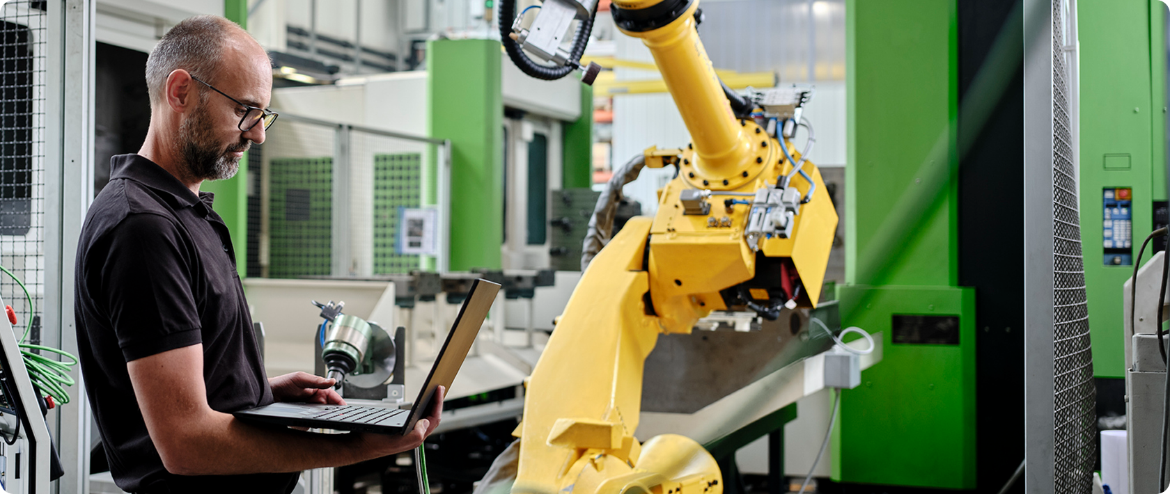
Talk to an Expert
Ready to overcome your challenges and unlock the full potential of your robotic applications? Contact our expert team today.