


Technical Paper Overview
Understanding Pulse Width Modulated CO₂ Laser Operation
Cavity rise/fall time, not PWM input, decides whether you see pulses.
The PWM signal driving a CO₂ laser is a simple square wave: 0V low, 5V high, frequency and duty cycle. The optical output emerging from the laser cavity is not simple. Cavity rise/fall time (~50-100 µsec), RF architecture limits, and CW-vs-Pulsed design choices reshape that square wave into output that may or may not pulse, may or may not match the duty cycle linearly.
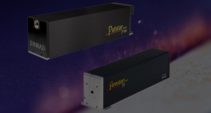
This technical paper from Novanta authors Justin Conroy and Malte Hemmerich walks through PWM-to-optical-output behavior on RF-driven CO₂ lasers — using the Synrad Firestar ti100 (CW: >100W, 160 kHz max, 0-100% duty cycle) and Synrad Pulstar p100 (pulsed: 400W peak, 35% max duty cycle) — at nine duty-cycle × frequency combinations, demonstrating exactly when output looks pulsed, when it smooths into CW, and why.
Key takeaways include:
- Why the PWM input signal is simpler than the actual laser optical output — and what gets lost in translation
- How laser cavity rise/fall time (~50-100 µsec) interacts with PWM frequency to determine pulses vs sawtooth vs smooth CW
- When to specify CW: vector marking, precision cutting of acrylic and labels, heat-treating
- What pulsed delivers that CW can’t: 2-4× peak power for drilling, metal piercing, reduced HAZ on sensitive materials
- A practical 9-setting matrix (3 frequencies × 3 duty cycles) documenting actual optical output for both lasers
Download the full technical paper for the side-by-side oscilloscope-style output graphs (ti100 and p100 at nine duty-cycle and frequency combinations), the tickle-signal explanation, and the CW-vs-Pulsed application matrix you can use to specify the right CO₂ laser architecture for your process before commissioning the line.