Locate the Liberty* MDrive Software Suite for download at the below link:
User Interface Software
Once installed on your PC, open the Liberty* MDrive Software Suite and select “Install Liberty* MDrive Ethernet Interface”. This will install the TCP/IP utility within the Liberty* MDrive Software Suite for use.
After installing this utility, a green check mark will be placed by the new command button that states “Launch Liberty* MDrive Ethernet Interface”. Select the command button with a single mouse-click. You should now see the Ethernet Interface software utility launch.
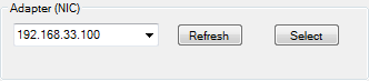
Select “Refresh” in the upper left hand corner of the screen to insure your “Adapter (NIC)” list is current with your PC settings:
Figure 1: Refresh adapter list
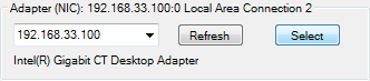
After selecting the proper “Adapter (NIC)” IP address that your PC is set up to communicate with the Liberty* MDrive in the drop down box provided, choose the “Select” button to the right of “Refresh” to solidify the selection. You should see a similar recognition as the image below:
Figure 2: Select Adapter (NIC) IP
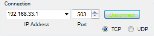
We now need to physically connect to the motor to insure the application protocol over Ethernet is set for Modbus TCP/IP. To do this, locate the “Connection” area in the upper right hand side of the TCP/IP utility and enter your IP address in the “Connection” box. For a first time Liberty* MDrive user, all of our drives come from the factory with an IP address of 192.168.33.1. Once the IP address has been entered, choose “Connect” to the right of the “Connection” box where you entered the device IP address. You should have a similar screen as shown in Figure 3 below:
Figure 3: Select Liberty* MDrive IP address
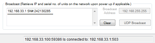
If you are successfully connected to the LMD device you will also see confirmation in the center of the TCP/IP utility at the bottom of the screen. Figure 4 below shows a successful connection between (NIC) 192.168.33.100 and LMD device 192.168.33.1:
Figure 4: Successful connection to the Liberty* product
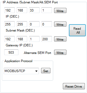
We now are able to read and write values for the connected device to configure it properly in your network. For this example we are going to keep the default IP address of 192.168.33.1 and insure the Ethernet Application Protocol is set to Modbus TCP/IP. By selecting “Read All” in the center of the TCP/IP utility, you can see what has been set in the device you are working with:
Figure 5: Select the Modbus/TCP application protocol
In this case, the motor has already been set to “Modbus/TCP” in the Application Protocol section, and the device IP address has been set to 192.168.33.1. If you wished to make changes, you simply would edit the proper fields, select “Write” (or “Set” for the Application Protocol), and then cycle power to the drive so the updated information can take effect in the device.
Once you have your IP settings and Application Protocol selected, you now can proceed to the Proface GP-Pro EX software to set up your HMI to talk to the LMD device.
HMI Setup
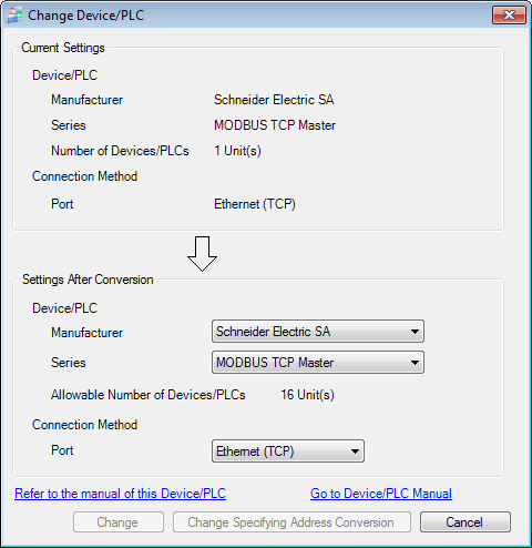
In the “Device/PLC” section of the GP-Pro EX software you need to select the “Schneider Electric-SA” Modbus TCP Master Driver from the pull down list. This is the common Modbus TCP driver created by Pro-face and works for many Modbus based devices, not just Schneider products. See Figure 6 below:
Figure 6: Select Modbus/TCP driver
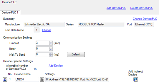
Insure that after selecting the proper Device Driver from above, you set the correct IP Address of the device you wish to talk to over Modbus. This is done right below the Device Driver selection area in the “Device/PLC” section of their project settings. In the attached project I kept the motor default IP address, which is 192.168.33.1.
Figure 7: Set the Liberty* product’s IP address
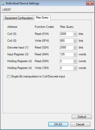
Once the IP address is set, you then need to change the “word” values for the holding registers in the “Max Query” section of the “Industrial Device Settings” tab you used to set the IP address. The last two holding register values for “Holding Register (4) Read” and “Holding Register (4) Write” need to be set to “2”. See below:
Figure 8: Configure holding register values
Once these communication settings are set, you then can begin to build your project as you see fit. The only other critical piece of information to realize when working with the Pro-face device is that the Proface register mapping starts at a value of “1” and we (Novanta IMS) start at a value of “0”. So when working with our Modbus register map, you just need to add a value of 1 to any starting address for the register you want to access. For example, our slewing command, SL, has an address of 120 in our map. For the Pro-face device you would want to select the starting address to be 121. An example of this can be seen below in the Proface environment:
Figure 9: Proface GP-Pro EX project environment
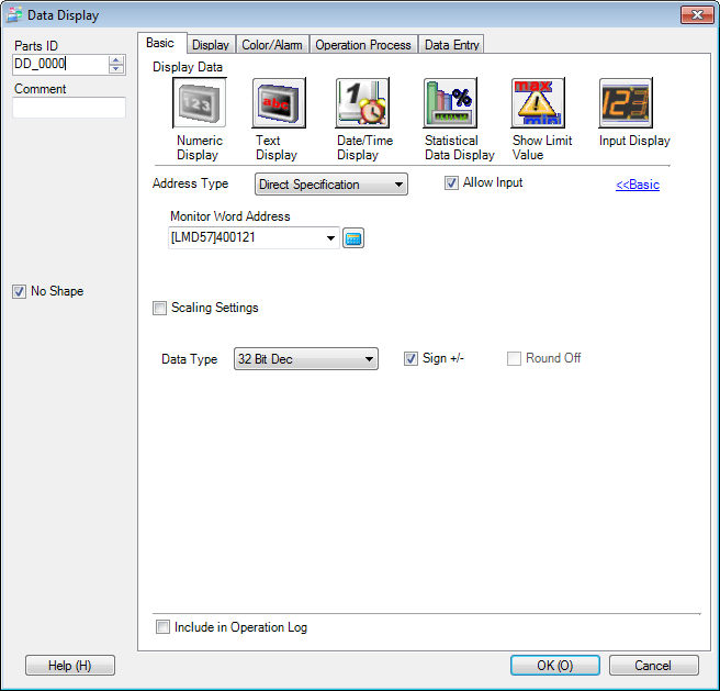
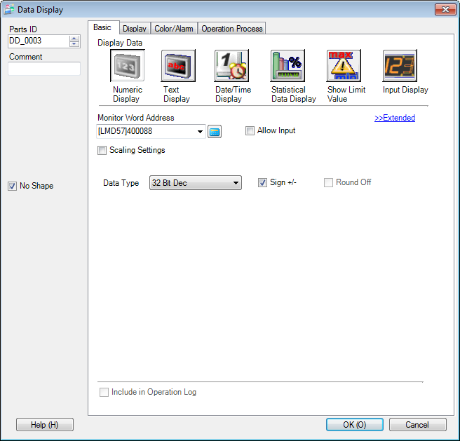
Finally, the last piece of advice is when selecting the proper length of the register to be read or written to. Many of our registers are going to be 32-bit decimal to accommodate for the larger values in micro stepping units but others are going to be 16-bit. This will be register value based and we can assist where needed. Here is an example below of reading back the motor position (P) over Modbus in the Proface software:
Figure 10: Verify correct register length
*Previously Lexium