


Position sensors are very diverse, but in the world of high performance automation, the encoder is a critical element. Position sensor encoders provide feedback for both rotary and linear servo motor control, as well as position information for metrology applications.
What are Rotary Position Sensors?
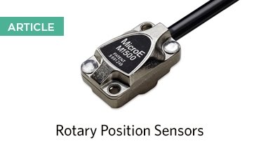
Rotary position sensors are a type of encoder that measure the angular position or displacement of an object, such as a shaft or motor, in a circular or rotational motion.
These sensors generate an output signal that varies depending on underlying technology and principle of operation. It is based on the same basic principle as a linear position sensor, except the device translates angular positions into useful output signals. Rotary encoders may be absolute or incremental. Read the article linked below to learn more about the working principles of rotary position sensors:
Types of Rotary Position Sensors
There are many different types of rotary position sensors, each with their own unique properties and functionality. This includes:
Rotary Potentiometers
Rotary potentiometers are a type of sensor consisting of a resistive element and a wiper which is connected to a rotating shaft. As the shaft rotates, the wiper moves along the resistive element, changing the level of electrical resistance.
These sensors are most commonly used in devices that require precise position feedback, such as joysticks, steering systems, volume controls, and a variety of industry control systems.
Rotary Encoders
A rotary encoder is a sensor that measures the rotational movement of a shaft and converts this into an electrical signal output. This signal can be used to indicate the precise positioning and speed of the shaft/object.
Absolute
An absolute rotary encoder provides a unique code corresponding to each distinct angular position of the shaft. This ensures that the exact position of the shaft is always known, even after power loss.
Incremental
An incremental rotary encoder generates signals in the form of pulses that track the relative movement of the shaft. However, it does not assign a specific code to each angle of rotation, meaning the exact position of the shaft is not retained – only changes in movement are recorded.
Hall Effect Sensors
Aptly named after the Hall Effect, Hall Effect sensors detect angular position and speed by measuring the voltage difference that occurs when a conductor is exposed to a magnetic field. The key advantage of these sensors is that they don’t require direct electrical contact to measure positioning, as they rely on magnetic fields. However, this also makes them more susceptible to interference from nearby electrical wires and magnets.
Hall Effect sensors are commonly used in vehicles to measure wheel speed and in smartphones to detect screen orientation.
Resolvers
Resolvers operate similarly to transformers. They contain 3 coils; two which are stationary (known as stators) and one that rotates (known as the rotor). Resolvers in motion control systems measure the angular position of rotating shafts by generating two output signals: a sine and a cosine wave, based on the rotor’s position relative to the stator. These signals allow the system to calculate the exact angular position of the rotor by taking the ratio of the sine and cosine values. From the rate of change in position, velocity and direction can also be found.
What are the Common Applications of Rotary Position Sensors?
Rotary position sensors are used in a wide variety of sensing applications, within a range of industries. Here are some of the most common applications of these sensors:
Automotive Systems
Used in vehicles for functions like throttle position sensing, steering angle detection, and transmission control.
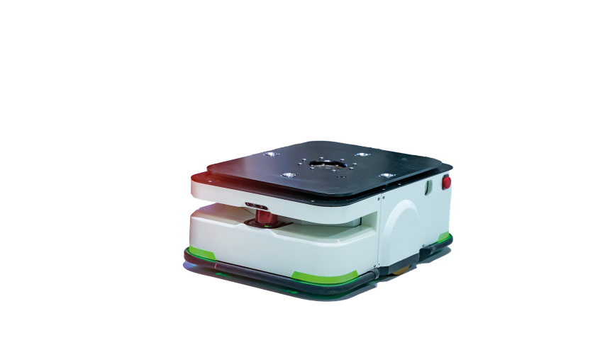
Industrial Automation
Employed in machinery for monitoring and controlling rotational movements, such as in robotics, CNC machines, and conveyor systems. In warehouse automation, these sensors play a crucial role in automated guided vehicles (AGVs) and autonomous mobile robots (AMRs), ensuring accurate navigation, positioning, and movement.
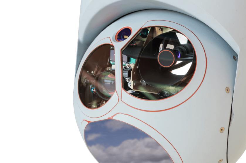
Field Robotics
Critical in agricultural and construction robotics, rotary position sensors help monitor and manage robotic arm positions and vehicle steering, enhancing precision and efficiency in challenging outdoor environments.
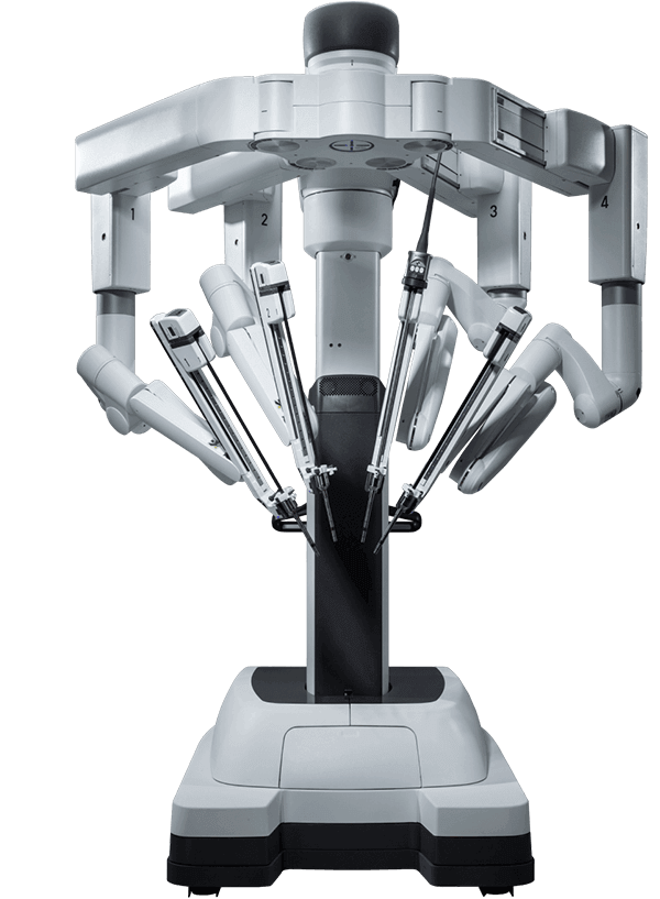
Surgical Robotics
Integrated into surgical robots to enable precise control of robotic arms and tools, ensuring accuracy and reliability during minimally invasive procedures and complex surgeries.
Humanoid Robotics
Used to replicate human-like movements in humanoid robots, these sensors assist in controlling joint angles, arm positions, and balance, enabling realistic motion and interaction.
Consumer Electronics
Found in devices like joysticks, video game console controllers, smartphones, and digital cameras for functions such as user input and image stabilisation.
Home Appliances
Integrated into devices like washing machines and dishwashers to manage and monitor motor positions and settings.
And much more.
Position Sensor Technologies
Rotary position sensors can be further defined based on the underlying technologies. Several sensor types can be used for both absolute and incremental position monitoring. The following is a brief selection of some of the primary types of sensor technologies:
- Capacitive position sensors
- Inductive sensors
- Magnetic position sensors
- Optical sensors
- Potentiometric position sensors
- Ultrasonic sensors
Although different sensing paradigms are preferred for different applications, optical position sensors typically offer the greatest accuracy and the highest resolution.
Optical Rotary Encoders
Optical encoders use photosensitive detectors and optical gratings to precisely indicate absolute or incremental position for rotary sensors. Interferential systems eclipse both transmissive and reflective encoders in terms of accuracy, compactness, repeatability, and resolution. They generate precise position data by impinging a laser beam on a diffraction grating printed on the rotary scale. This diffracts the incoming beam, generating a high contrast interference pattern on the detection array. Optical encoders require a readhead, which is used regardless of the scale being used.
Mercury I Interferential Optical Rotary Encoders
At Celera Motion, we offer compact interferential optical encoders with the MercuryTM Series encoders. The Mercury™ Series optical encoders are position sensors that can be used for rotary position sensing. The miniature rotary sensor fits into tight spaces and has wide alignment tolerances for easy installation. Mercury Series M1000 has analog outputs that can be interpolated by the customer’s electronics for resolution up to 5 nm.
Mercury™ M1000 Rotary Grating Specifications
| Highest Accuracy Class | /- 2 arc-seconds |
|---|---|
| Diameters | up to 108mm |
| Index | Yes |
| Material | Soda lime glass |
| Coefficient of Thermal Expansion | 8ppm/°C |
| Mounting | Hub |
Mercury™ Series M1000 Rotary Scale Specifications
Mercury II Optical Rotary Encoders
The Mercury II™ Series can also be used for rotary applications. This technology achieves the highest resolution in its class, up to 1.2 nm. Low cyclical error, surpassing other 20μm encoders, enables smooth velocity control, high precision, and fast positioning. Low jitter and low power consumption are important specifications when choosing a position sensor for your application, and the Mercury II delivers this with optimal performance. Broad alignment tolerances, a full /-2 degrees, makes Mercury II the easiest and the fastest rotary position sensor to install and align – in under 30 seconds!
Mercury II™ 5800 Rotary Grating Specifications
| Highest Accuracy Class | /- 2 arc-seconds |
|---|---|
| Diameters | up to 108mm |
| Index | Yes |
| Material | Soda lime glass |
| Coefficient of Thermal Expansion | 8ppm/°C |
| Mounting | Hub |
Mercury II™ 5800 Rotary Scale Specifications
Mercury II™ 6000 Rotary Grating Specifications
| Highest Accuracy Class | /- 2 arc-seconds |
|---|---|
| Diameters | up to 120mm |
| Index | Yes |
| Material | Soda lime glass |
| Coefficient of Thermal Expansion | 8ppm/°C |
| Mounting | Hub |
Mercury II™ 6000 Rotary Scale Specifications
Rotary Inductive Encoders
Inductive position sensors work on the basic principles of resolvers using laminar windings to generate inductive fields. Rather than using adjacent conductors (coil windings), induction sensors use PCB traces which are excited by frequencies in the nominal range 1-10MHz. There are enormous benefits to using printed traces rather than adjacent windings, including lower cost, smaller device formats, and greater device integration into multi-layer PCBs.
At Celera Motion, we supply inductive angle encoders with the Ultra IncOderTM Series. This pre-calibrated rotary position sensor is a non-contact system trusted by aerospace, industrial, and medical device manufacturers around the world.
For more information on which rotary position sensor would best suit your application needs, please contact a member of the Celera Motion team today.