


Introduction to Alignment of the ChipEncoder Series
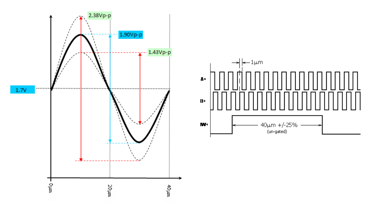
Optimal alignment of the CE300 (7mm x11mm package) or the CE-40GC (6mm x 6mm package) is achieved through adherence to MicroE’s published interface drawings and can be verified and fine -tuned using the Sin and IW signals. Sin is available on pad 14 of the CE300 and pad 3 of the CE40-GC. It is a sinusoidal function that rides on a 1.7V offset and varies with position. IW is found on pad 24 of the CE300 and pad 16 of the CE-40GC. It is an active-high TTL pulse that occurs each time the index mark on the scale is passed.
Both signals must be present and within the following specification limits in order to ensure proper encoder function.
Sin = 1.90Vpeak to peak ±25%
IW = 5V square pulse, 40um wide ±25%