


How does an inductive sensor work?
This article explains the technology of an inductive sensor or inductive encoder. This device is closely based on the resolver. It is instructive to discuss the resolver before exploring the inductive encoder.
Resolvers
Resolvers are based on the principle of electromagnetic induction – an alternating current in one conductor generates a changing magnetic field around the conductor. This magnetic field can induce an alternating current in an adjacent conductor. The magnitude of coupling from one conductor to another depends on the rate of change of magnetic field and the relative position and geometry of the conductors.
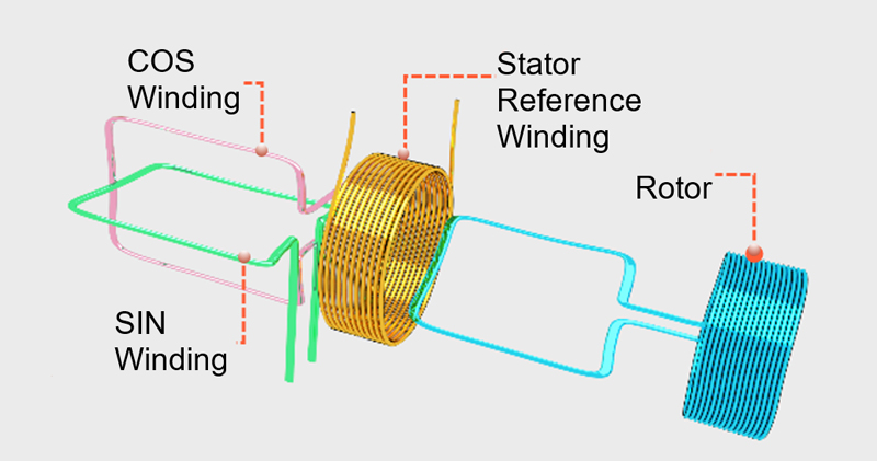
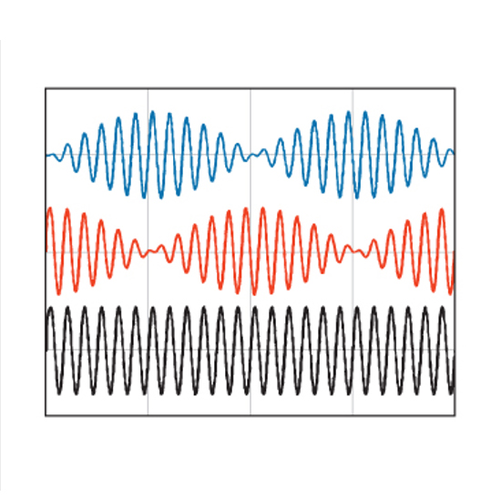
As shown below, a 5kHz (typ.) sinusoidal reference voltage in the stator induces a sinusoidal voltage in the rotor winding. A second, axial, rotor winding then induces a voltage in two axial signal windings displaced by 90º back on the stator. The amount of coupling into the stator windings is a function of the relative position of the rotor which effectively amplitude modulates the stator signals as shown.
In the illustration above the rotor is shown outside the stator for clarity. The radial windings on the stator interact with only the radial windings on the rotor. In turn, the axial windings on the rotor interact with only the axial windings on the stator. This is to avoid the stator reference winding coupling to the stator signal windings. Winding a resolver is not trivial and the end result is a heavy, bulky device. The resolver does, however, have unmatched ruggedness as there are no electronics or fragile parts in the device.
Resolvers are available in various “speeds”. A single speed resolver has one electrical sinewave cycle per rev and provides absolute position information with limited resolution. A “multi-speed resolver” is wound for a higher number of electrical cycles per rev improving resolution. The higher ratio of electrical to mechanical cycles also helps minimize the effects of mechanical error sources. Multi-speed resolvers are no longer absolute and are more expensive and typically even more bulky.
Inductive Sensors
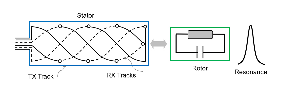
The absolute inductive encoder, or inductive sensor, is based on the same electromagnetic induction principle as the resolver but uses PCB traces rather than coil windings. The TX track on the stator is excited by specific frequency in the range 1-10MHz. This signal inductively couples into target with a resonant LC circuit. The target magnetic field induces a sinusoidal current in stator RX track. The RX track is sinusoidal in shape which effectively amplitude modulates the induced signal. A second RX track displaced by 90º carries a cosine signal. The sin/cos signals are interpolated and output as BiSS-C, SSI or in some versions AqB signals.
The RX tracks on the stator are analogous to a twisted pair wire. The balanced dipole effect cancels electric fields induced in the RX tracks from the changing magnetic field on the TX track. The RX track responds to changing magnetic field on the target only. The RX tracks also reject external electromagnetic interference. Undesirable induced stator currents are also rejected based on frequency and phase.
The main RX tracks with one sin/cos cycle per rev defines absolute position. A secondary track with multiple cycles enhances resolution. More typically the main TX track has multiple cycles (9 for example) combined with a secondary track with a number of cycles not a multiple of 3 – every position within one rev is defined by two unique readings.
The use of PCB traces versus the resolver’s windings brings significant advantages including: reduced cost, size and weight; form factor flexibility including curvilinear; elimination of inaccuracies from the winding process; for safety-related applications multiple sensors can be located in the same space by using multi-layer circuit boards.
The PCB material is environmentally very stable. The option for remote electronics further increases ruggedness. The 360º sensor improves eccentricity error tolerance.
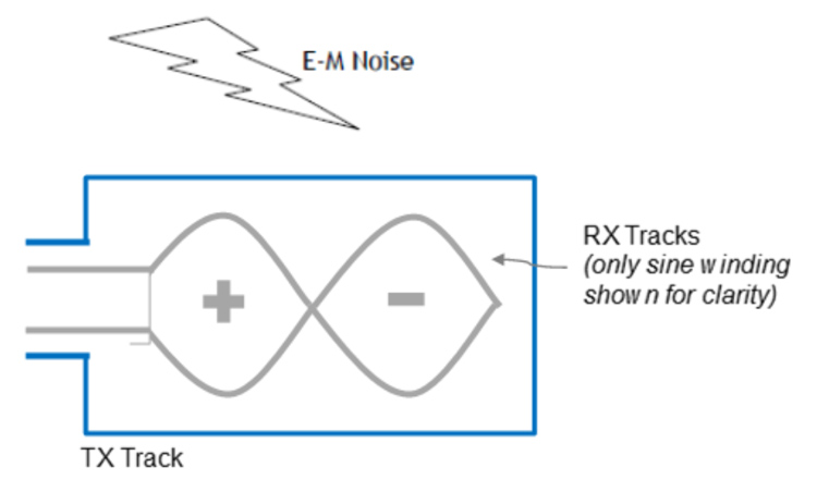
Figure. 1 – RX track and TX tracks for inductive encoders
Types of inductive sensors
Proximity Sensors
In a simple proximity (or ‘prox’) sensor an electrical power supply causes an alternating current to flow in a coil (sometimes referred to as a loop, spool or winding). When a conductive or magnetically permeable target, such as a steel disk, approaches the coil, this changes the coil’s impedance. When a threshold is passed, this acts as a signal that the target is near. Proximity sensors are typically used to detect the presence or absence of a metal target and the output often emulates a switch. This type of inductive sensor is commonly used where a traditional switch might prove problematic – notably where lots of dirt or water is present. You will see lots of inductive proximity sensors next time you go through a car wash or glance at the landing gear when you board an aeroplane.
Variable Inductance Sensors
Variable inductance sensors and variable reluctance sensors typically produce an electrical signal proportional to the displacement of a conductive or magnetically permeable target (normally a steel rod) relative to a coil. As with the proximity sensor, a coil’s impedance varies according to the displacement of the target when the coil is energised with an alternating current. Such sensors are often used to measure the displacement of pistons in pneumatic or hydraulic rams. The piston can be arranged to pass over the outer diameter of the sensor’s coil.
Synchros
Synchros are another form of inductive position sensor and they measure the inductive coupling between coils as they move relative to each other. Synchros are normally rotary and require electrical connections to both moving and stationary parts of the sensor (typically referred to as the rotor and stator). They can offer extremely high accuracy and are used in industrial metrology, radar antennae and telescopes. Synchros are notoriously expensive and are increasingly rare, having mostly been replaced by (brushless) resolvers. These are another form of inductive position detector but electrical connections are only made to windings on the stator.

LVDTs, RVDTs and resolvers measure position from the change in inductive coupling between coils, usually referred to as primary and secondary windings. The sensor’s primary winding couples energy into the secondary windings but the ratio of energy coupled into each of the secondary windings varies in proportion to the relative displacement of a magnetically permeable target. In an LVDT, this is usually a metal rod passing through the bore of the windings. In an RVDT or resolver, it is normally a shaped rotor or pole piece that rotates relative to the windings arranged around the periphery of the rotor. Typical applications for LVDTs & RVDTs include hydraulic servos in aerospace aileron, engine and fuel system controls. Typical applications for resolvers include brushless electric motor commutation.
Advantage of Inductive Position Sensors
A significant advantage of inductive position sensors is that the associated signal processing circuitry need not be located in close proximity to the sensor’s coils. This allows the sensing coils to be located in harsh environments, which might otherwise preclude other technologies – such as magnetic sensors or optical encoders – as they require relatively delicate, silicon-based electronics to be located at the sensing point.
Technology Comparison – Inductive Sensors, Inductive Encoders & Resolvers
Resolvers and inductive sensors / encoders deliver superior precision combined with exceptional environmental ruggedness. As discussed, the inductive sensor has numerous advantages versus the resolver particularly size, weight and ease of customization.