


precision medicine
FAQs
Benchtop Visible Range Spectroradiometers
Yes. Configurable optics, accessories, and software modes enable one benchtop system to support display calibration, imaging validation, illumination measurement, and R&D testing across multiple medical platforms.
Photo Research benchtop spectroradiometers deliver traceable, repeatable measurements essential for meeting regulatory standards and maintaining consistent performance across production and service lifecycles.
Benchtop spectroradiometers provide higher stability, sensitivity, and dynamic range than handheld instruments, making them ideal for precision calibration, validation, and quality control of medical displays and lighting systems.
Complete Display Solutions
Yes. We support long?term OEM programs through a robust, global supply chain, controlled component sourcing, and proactive lifecycle planning suited for regulated environments.
We offer customization across key parameters including display size, resolution, brightness, touch technology, controller interfaces, viewing angles, and mechanical integration to match your exact system requirements.
Customers work directly with our engineering team to define specifications, validate performance, and streamline integration—reducing development risk and accelerating time to production.
Displays
Check in the Panel Specifications for your display module. They often contain mounting guidelines. If not, you can also refer to the general policies in one of these documents:
Resistive Touchscreen Integration
Projected Capacitive Touchscreen Integration
Make sure Windows isn’t renaming the file for you. Some web browsers insist on renaming the file .STEP to .txt. To work around this, you can either do a right-click on the link, select Save as…, or rename the file to a .STEP file.
Yes, there is. We recommend getting a microSD extension.
Learn about what I/O options you have and what they can do. To see which options are supported by each module, visit the Technical Specifications page.
A resistive touch screen consists of several layers, and a capacitive touch screen consists of an insulator coated with a transparent conductor. Compare resistive vs. capacitive touch.
Some people believe you need a projected capacitive touch screen for latex gloves. However, resistive touchscreens work under pressure, so gloves, stylus, or anything that pushes the touch screen will work.
Reach Technology does not support any OLED (organic light emitting diode) displays.
If you want the lowest cost, you buy the displays yourself. However, we cannot provide technical support for displays that we don’t sell. Suppose you’re not already aware of the vagaries of the LCD business and especially of the availability of LCD products. In that case, you might want to read how the LCD business is very different from others.
Reach Technology began in 1988 and is still supporting products designed in the mid-1990s. As long as there are customers for a particular board and parts are available, we will continue to make it. Our job is to keep the product current and deal with part obsolescence issues. The user interface will stay the same. Read more about our commitment to long-term supply.
We specialize in displays for medical and industrial applications and only support LCD form factors that are “industry standard,” which means they will be available for 5-7 years or longer. The smaller displays (under 4.3?) tend to be device-specific and therefore change every 18 months. Suppose you’re not already aware of the vagaries of the LCD market and especially of the availability of LCD products. In that case, you might want to read, “The LCD business is very different from others.”
G3 Displays
For detailed instructions, see the G3 Manual .
For detailed instructions, see the G3 Manual .
For detailed instructions, see the G3 Manual .
No.
Yes, for some 7″ panels and all panels larger than 7″.
Primarily to avoid breaking the module. It will also improve your product reliability by preventing system crashes from filling the root filesystem.
It is a Device Tree Blob. Most desktop Linux machines actively probe for installed hardware to load and initialize various drivers. This can be a slow yet tedious process. To avoid the time required to probe in general, embedded Linux devices use a pre-defined, binary DTB to tell the kernel what is on the board and how to talk to it.
You need to install the boot-select jumper. Check the appropriate controller hardware manual.
You need to set your DTB.
Each controller board in the G3 family supports a subset of panels. See the table below for details. Panels are driven at native resolutions, as most do not support multiple display timings.
Supported LCD Panel Resolutions
Mnemonic
Resolution
WQVGA
480 x 272
WVGA
800 x 480
XGA
1024 x 768
WXGA
1280 x 800
Need something else? Let us know. We are constantly working on new modules.
Hospital Asset Management
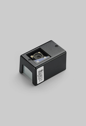
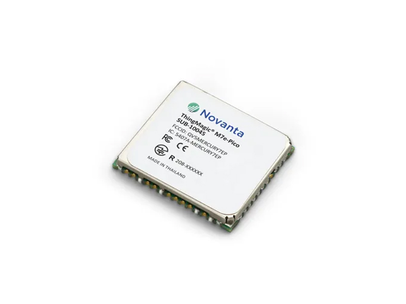
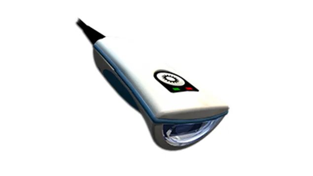
Medical inventory management software, RFID modules, barcode scanners and even machine vision technology can all form part of a medical inventory tracking system. As we specialize in developing custom engineering solutions, every system will include slightly different components, so it’s best to get in touch to discuss your options.
Environments that can benefit from healthcare asset tracking solutions include hospitals, pharmacies, and clinics, with healthcare staff, hospital security personnel, and patients all benefiting from RFID medical asset tracking solutions in different ways.
Increased efficiency and enhanced productivity are two of the main benefits of RFID hospital asset tracking. RFID technology automates manual stocktaking and auditing tasks to improve inventory management, save time, and improve productivity. Enhanced hospital asset management also reduces the risk of assets being lost or mislaid, further enhancing efficiency.
Our RFID-powered healthcare asset tracking solutions help hospitals and other medical environments to stay compliant with reporting requirements by providing real-time visibility into the status and location of people and equipment. This is vital for maintaining accurate records to support auditing and compliance reporting.
Hospital asset tracking helps clinicians to deliver an enhanced standard of patient care by supporting inventory management and asset tracking to ensure important medications and pieces of equipment are always available when needed. RFID hospital tracking also provides greater visibility over important assets to help keep everything operating smoothly, while reducing the risk of assets being lost or misplaced, and of medications running low or going out of date.
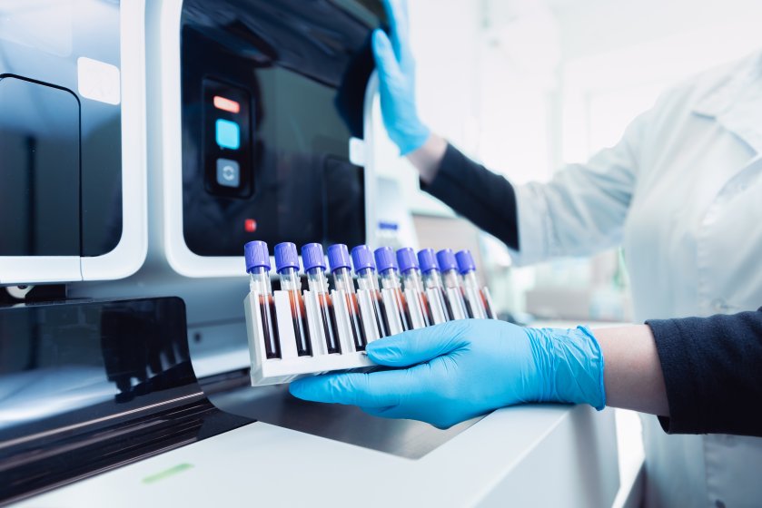
Lab automation
In-vitro diagnostic (IVD) tests are performed on biological samples taken from the human body, like blood, tissue, or other bodily fluids. These tests, conducted outside the body (in vitro), are used to detect diseases or infections and in monitoring a patient’s health.
The information provided by in-vitro diagnostic testing is essential for healthcare providers in making accurate diagnosis and guiding their treatment decisions. IVD testing is a critical tool in disease management, improving patient outcomes, and contributing to overall public health.
OEMs offer many advanced capabilities designing products for efficient high-throughput, testing with rigorous quality controls to ensure reliability, and complying with industry regulations to guarantee a safe product.
OEMs can integrate cutting-edge technologies into in-vitro diagnostic devices, such as microfluidics for precise fluid handling, biosensors for enhanced sensitivity, and digital health solutions for connectivity and data analysis. These types of technologies improve the accuracy, efficiency, and overall performance of IVD tests.
OEMs provide many laboratory automation devices including automated sample tracking systems, reagent authentication technologies, machine vision automation for quality control, and automated cell counting systems. These types of solutions streamline laboratory workflows and improve testing accuracy and efficiency.
Machine vision automation enhances quality control by using advanced imaging technologies to detect errors and inconsistencies in samples, reagents, and test results.
Light Source Calibration
The system provides a highly uniform, diffusely radiating integrating sphere with real?time luminance monitoring and stable color temperature control—ensuring repeatable, traceable calibration across photometric, radiometric, and spectroradiometric instruments.
Yes. Modular integrating sphere sizes, multiple exit port options, adjustable luminance over six decades, and optional spectral filters allow the system to scale and configure easily for a wide range of instruments and calibration setups.
Automated lamp control, surge?protected power ramping, precise current regulation, and elapsed?time tracking extend lamp life, minimize downtime, and reduce recalibration and replacement costs over long?term programs.
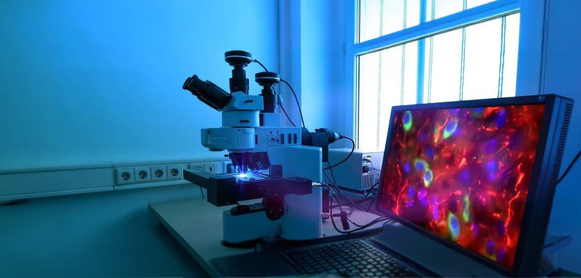
Microscopy
There are many benefits of using machine vision technology within a microscopy camera, including the ability to achieve higher-resolution, more detailed images, while faster frame rates support improved observation. The technology can also support microscopy automation, significantly speeding up analytical processes.
A microscopy camera featuring machine vision technology can be used in various applications, including neurosurgery, ophthalmology, otolaryngology, and plastic reconstructive surgery.
An automated microscopy system powered by machine vision can help to support patient outcomes by speeding up diagnoses, which are more likely to be accurate due to the improved clarity and detail offered by the advanced microscopy camera.
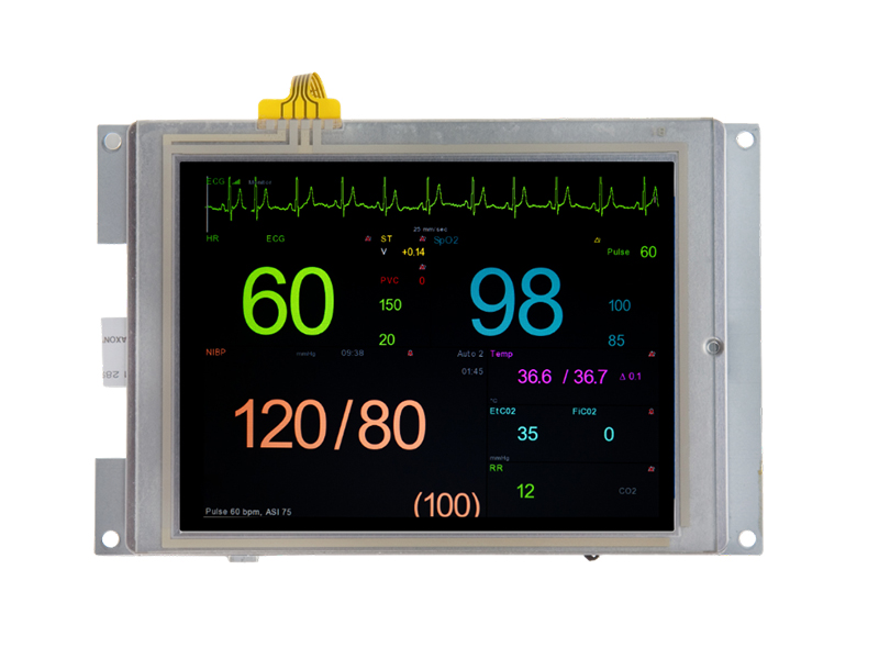
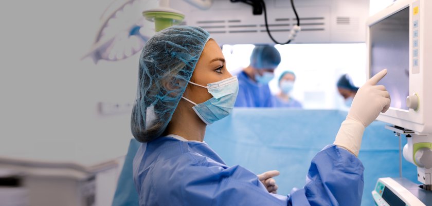
Monitors
Yes. Our medical monitors are designed with healthcare workflows in mind, supporting cleanliness requirements, long?term product availability, and consistent performance across clinical, diagnostic, and point?of?care environments.
Absolutely. WE offer flexible configurations including screen size, brightness, touch options, and mounting support—allowing monitors to be tailored for carts, kiosks, imaging systems, nurse stations, and telemedicine platforms.
We deliver direct access to engineering expertise, guiding customers through integration, compliance considerations, and lifecycle support to ensure smooth deployment and long?term product continuity.
NIR Spectroradiometers
NIR spectroradiometers extend measurement capability beyond the visible range, enabling accurate characterization of near?infrared light sources, materials, and imaging systems that visible?only instruments cannot measure reliably.
High?performance NIR spectroradiometers are designed for stability, low noise, and traceable accuracy, delivering repeatable spectral measurements essential for validation, calibration, and quality control applications.
Yes. Configurable optics, measurement apertures, accessories, and software modes allow a single NIR spectroradiometer to adapt across R&D, production, and field environments while supporting diverse testing requirements.
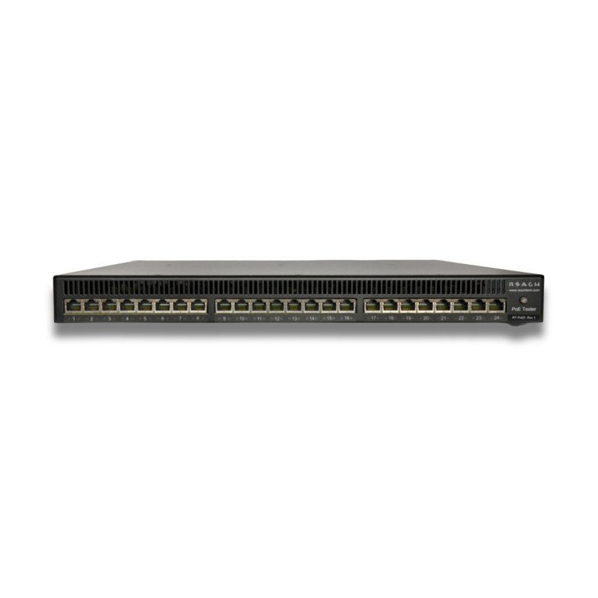
PoE5
Legacy detect/Cbad are 10uF.
The load is designed to have a 4.7A/ms current slew rate. All 24 ports are designed to be able to come to full load from power good in under 150ms.
Texas Instruments TPS2372. IEEE 802.3bt PoE High-Power PD Interface with Automatic MPS & Autoclass.
All 24 ports are capable of providing load.
Each port has 47uF of bulk capacitance connected to the PSE after the PoE class is negotiated. All detection criteria defined in section 145.2.6.3 of 802.3bt are preserved during detection and negotiation.
As the data path is entirely passive, it supports 1G-10G traffic. All channels on all units are verified to provide a CAT-6A compliant data path before they leave the factory.
Portable Visible Range Spectroradiometers
Visible?range spectroradiometers ensure accurate luminance, color, and contrast measurement for medical displays and illuminated devices, helping maintain diagnostic consistency and regulatory compliance.
Photo Research spectroradiometers are engineered for long?term measurement stability and repeatability, supporting consistent calibration and quality control throughout a device’s lifecycle.
Yes. Configurable optics, accessories, and software modes allow a single instrument to support display calibration, lighting verification, and system validation across R&D, production, and field environments.
SLCD-N Displays
Contact our sales team for pricing or see inquire on our pricing page.
UART is the only serial bus we support: RS-232, TTL/CMOS, and on some modules, USB. We also support an RS-485 like addressed protocol over the UART.
Our display controllers do not directly support this J1939 vehicle communications standard. If you found a host computer (ex., microprocessor board) that does use J1939, it may be possible to use the data from this protocol with our display controllers. The host computer needs either RS-232, TTL, or USB (depending on the module) to receive the data using our command set.
SLCD controller boards use PicoBlade connectors. They are made by Molex and are miniature (1.25mm pitch) which makes them hard to make by hand. International Component Technology can make these cables for you to use to connect to your microcontroller board.
You need to use the UTF-8 format of the character. For conversion between Unicode and UTF-8, see http://www.utf8-chartable.de/. In your case, the bullet character 0xB7 is c2 b7, so the text command would be:
utf8 on
t “xc2xb7” 100 100
Here’s a handy online conversion utility: http://www.ltg.ed.ac.uk/~richard/utf-8.cgi?input=b7&mode=hex
There are probably formulas to work these out in your application as well. Here is more detail than you might want: http://en.wikipedia.org/wiki/UTF-8
Here is an example of printing the special characters “, , and % in ‘C’ strings using our API.
void demoSpecialChars(void)
{
char buf;
sprintf(buf,”f 24?); // set font size 24
sendToSerialPort(buf);
sprintf(buf,”s 0 1?); // set black on white
sendToSerialPort(buf);
sprintf(buf,”z”); // clear screen
sendToSerialPort(buf);
sprintf(buf,”t ”%s”r”,”Backslash: \\“); // backslash in string
sendToSerialPort(buf);
sendToSerialPort(“t ”n”r”); // newline
// backslash as character
sprintf(buf,”t ”%s%c%c”r”,”Backslash: “,’\’,’\’);
sendToSerialPort(buf);
sendToSerialPort(“t ”n”r”); // newline
sprintf(buf,”t ”%s”r”,”Percent: %”); // Percent
sendToSerialPort(buf);
sendToSerialPort(“t ”n”r”); // newline
sprintf(buf,”t ”Percent: %%”r”); // Percent
sendToSerialPort(buf);
sendToSerialPort(“t ”n”r”); // newline
// Quote (need 2 to get one for SLCD, and one more to allow ” in string)
sprintf(buf,”t ”%s”r”,”Quote: \“”);
sendToSerialPort(buf);
sendToSerialPort(“t ”n”r”); // newline
// Quote as character
sprintf(buf,”t ”%s%c%c”r”,”Quote: “,’\’,’“‘);
sendToSerialPort(buf);
sendToSerialPort(“t ”n”r”); // newline
}
See Fonts for Embedded Touch Screen Development for a comprehensive explanation of working with fonts.
The “Vertical Mount” display module has mounting tabs on the long sides of the display module, with the tabs aligned vertically when the module is in landscape orientation.
The “Horizontal Mount” display module has these tabs on the short sides, with the tabs aligned horizontally when the module is in landscape orientation. The two options allow customers to fit a module into either a narrow or short space.
In both cases, the default orientation is landscape, with the long sides horizontal, but the modules may also be used in portrait mode with an alternate firmware load.
We suggest converters that have the FTDI chip inside from Digikey.
Popular development kits typically ship within one business day, while others may be built to order, our team will contact you to confirm an expected ship date. This quick fulfillment process helps teams accelerate prototyping and move efficiently into production.
Our display modules are built on a highly tuned embedded Linux environment and support multiple GUI frameworks, including Qt, GTK, WxWidgets, and LVGL. They also provide standard I/O interfaces such as USB, RS?232, RS?485, I²C, SPI, and CAN, along with web/IoT?ready tools like lighttpd, Node.js, Redis, and Mosquitto for connected applications.
Spectroradiometers
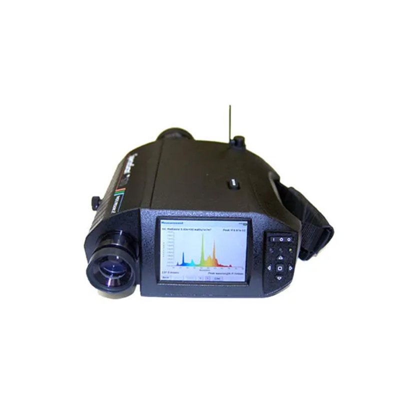
Overall, the accuracy of a spectroradiometer is determined by the precision of calibration, the quality of the optics, and the detector’s response characteristics. Many advanced models, such as the SpectraScan® series, spectral measurement resolutions as fine as a few nanometers and can provide measurements with an accuracy of better than ±1% in intensity and ±2% in color coordinates. This level of precision is vital for ensuring consistency in color reproduction and for developing lighting solutions that deliver the desired aesthetic vision in fields such as cinematography.
Spectrometers and spectroradiometers are analytical instruments used to measure properties of light and color. A spectrometer only measures the spectrum of light emitted, absorbed, or scattered by materials by analyzing the specific wavelength of light. In contrast, a spectroradiometer measures the intensity of light and color across a range of wavelengths. This is what makes spectroradiometers particularly desirable in applications that required a high-level of detail about light and color measurement.
Spectroradiometers work by capturing light and disecting the light wavelengths through a prism or diffraction grating. This dispersed light is then detected by sensors which convert the light into electrical signals that are proportional to the light intensity at each wavelength. This analysis provides precise and detailed measurement of the light and color in a given environment.
Spectroradiometers are used in multiple industries that require precise measurements of light or color. These colorimeter devices are commonly used to inform video production and cinematography in the film industry to refine visual outcomes. Industries such as automotive, aerospace and defense utilize spectroradiometers to enhance digital displays and vision technologies and improve the safety and reliability of digital devices.
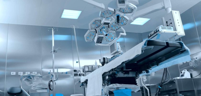
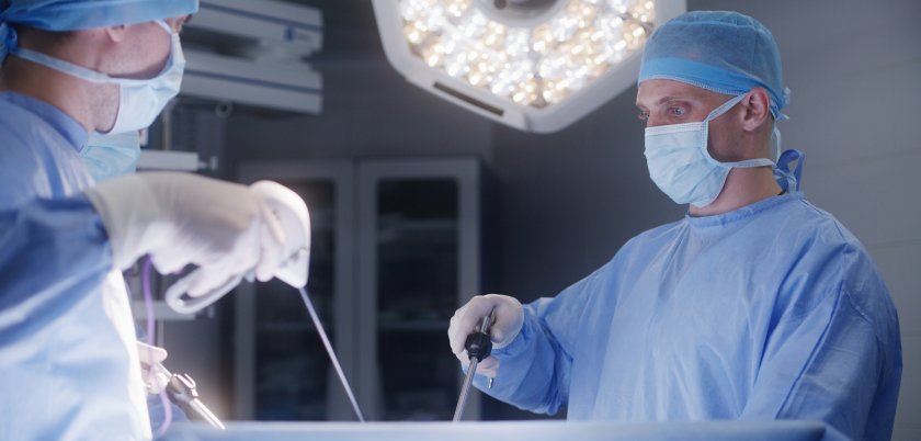
Surgical Imaging
Surgical imaging systems play a crucial role in enhancing surgical procedures by providing real-time, high-resolution images that enable surgeons to navigate complex anatomical structures with greater precision. These advanced surgical imaging technologies allow for better visualization of a patient’s organs, tissues, and blood vessels during operations. This enhanced visibility helps in minimizing surgical risks, reducing the likelihood of complications, and improving overall patient outcomes.
When choosing a surgical imaging system for a specific procedure, several key considerations must be addressed to ensure optimal results. First, it is crucial to evaluate the type of imaging modality best suited for the procedure. Additionally, consideration should be given to the system’s compatibility with existing surgical instruments and workflows, as well as its ease of use for surgical teams. Image resolution, portability, and real-time surgical imaging capabilities are also vital factors, particularly in complex surgeries where precision is paramount.
The use of surgical imaging systems in the operating room presents several common challenges that can impact the efficiency and effectiveness of surgical procedures. One significant issue is the integration of various imaging modalities, such as X-ray, ultrasound, and MRI, which can lead to complications if the systems are not compatible. Additionally, real-time imaging can be hindered by technical malfunctions or delays in image processing, negatively affecting the surgeon’s ability to perform the surgery.
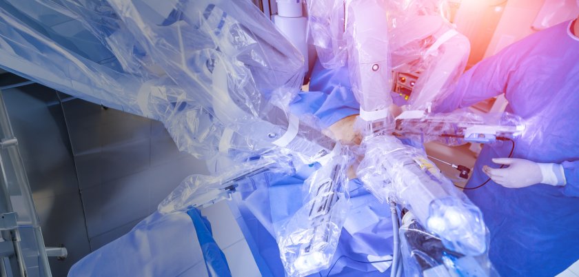
Surgical Navigation
Surgical navigation systems can be used in procedures including neurosurgery, orthopedic surgery, cardiovascular procedures, dental and ENT surgeries, and spinal surgery. In each case, the surgical navigation system can enhance precision to support patient outcomes.
Surgical navigation systems use machine vision technology alongside a computer system in order to provide real-time, high-resolution images of internal anatomy and surgical instruments. These surgical navigation technologies work together to deliver real-time visual feedback to the surgeon to enhance precision.
The key benefits of using a machine vision-powered surgical navigation system include improved image quality and resolution to enable a greater level of precision, as well as enhanced instrument tracking. Combined, these benefits can lead to more seamless procedures and improved patient outcomes.
A surgical navigation system featuring machine vision technology can help to support improved patient outcomes by enabling enhanced precision during surgery. As a result, the risk of complications is reduced, potentially leading to shorter recovery times.
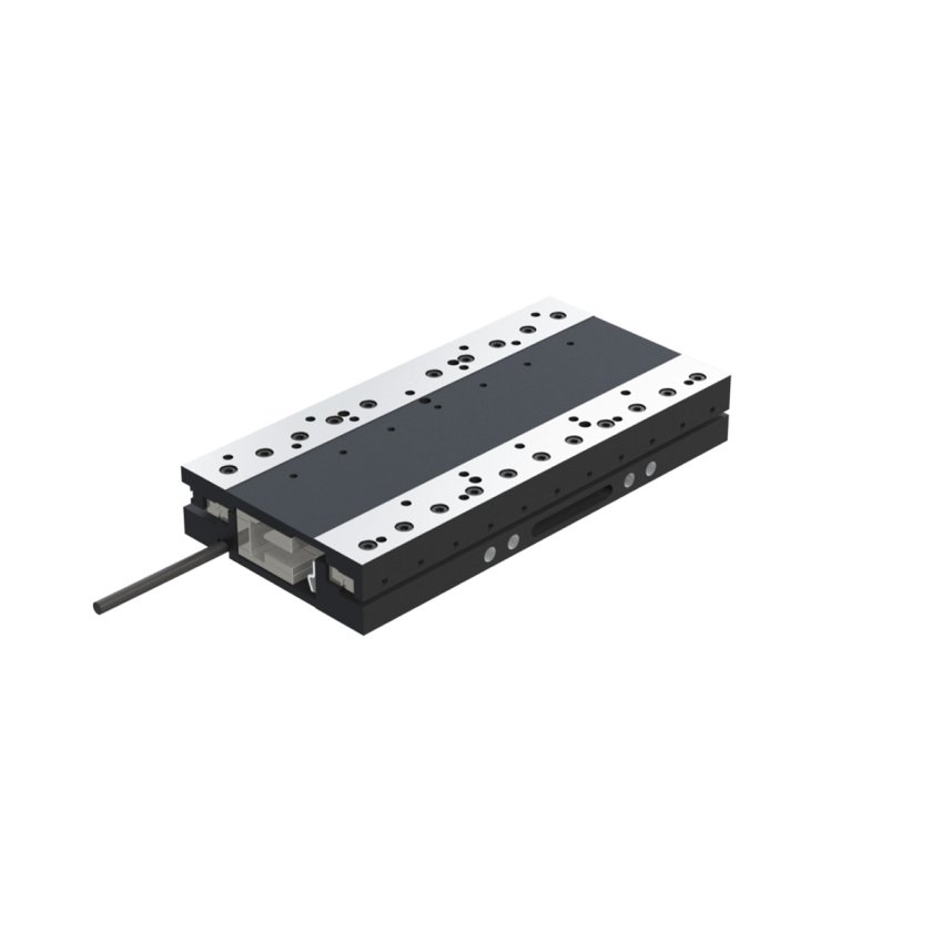
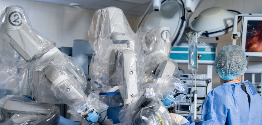
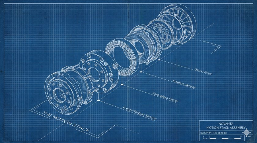
Surgical Positioning
Surgical positioning refers to the precise movement and stabilization of patients, instruments, or imaging systems during procedures. Accurate positioning is critical for improving surgical access, enhancing visualization, and ensuring patient safety, especially in minimally invasive and image-guided procedures.
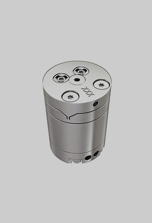
Novanta provides enabling technologies such as precision motion control systems, motors and drives, encoders and position feedback solutions, and high-performance controllers that work together to deliver smooth, accurate, and repeatable positioning in surgical environments.
Novanta solutions are designed for high accuracy and repeatability, supporting micron-level precision in demanding applications. This ensures consistent positioning performance critical for robotic-assisted surgery, imaging systems, and delicate procedures.
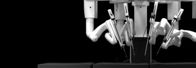
Yes. Novanta solutions are widely used in robotic-assisted surgery, providing the precise motion control and feedback required for accurate and controlled movement of instruments and imaging platforms.
Novanta surgical positioning solutions are commonly used in applications such as surgical tables, patient positioning systems, robotic surgical platforms, imaging and visualization systems, and minimally invasive or image-guided procedures.

Talk to an Expert
Ready to overcome your challenges and unlock the full potential of your robotic applications? Contact our expert team today.