


robotics and automation
FAQs
General
The motor constant (Km) of a motor is a ratio of the motor’s torque and the square root of the power dissipated. It is a numerical description of how well a motor can convert electrical energy into useful torque rather than resistive heat. It is a useful way to compare two motors. A motor with a higher Km will be able to output the same torque while staying cooler than an otherwise equivalent motor with a lower Km. Km should be an important consideration for any application that has thermal or efficiency limitations. Learn more about why Km matters for thermally limited applications here.
It is recommended that a motor be selected before the drive so that you can ensure the motor performance as stated on the datasheet. If you select a drive first, you may not have enough current as specified on the motor datasheet to meet the continuous torque requirement. As an example, say you selected a drive that supplies 6A of current. Then you select the Omni motor OPN060013A , with a continuous torque of 0.52Nm, which meets your system requirements. However, you later notice that that motor has a continuous current rating of 17A. This means that the continuous torque value of 0.52Nm was rated at 17A. If you only have 6A to supply to the motor, the continuous torque output will drop significantly. See the continuous torque calculation with limited current below. Continuous Torque = Kt*Continuous Current 0.52 = 0.03 * 17 X = 0.03 * 6 X = 0.18 Nm Omni motor and Ingenia servo drive compatibility chart.
Please contact an Applications Engineer for torque-speed performance curves. For performance, electrical, and mechanical specifications, please see our datasheets located on each frameless motor product page.
To convert between Kt_sine and Kt_trap, use the equation below. Kt_sine = 0.87 * Kt_trap Click here for more motor unit conversions.
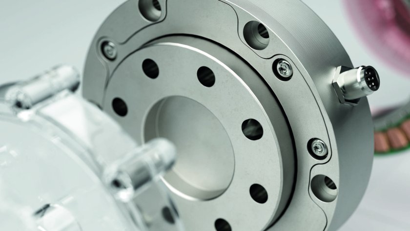
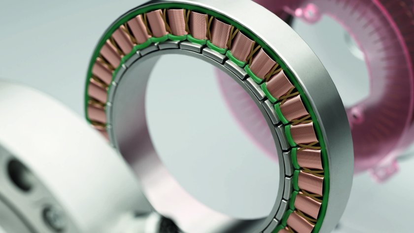
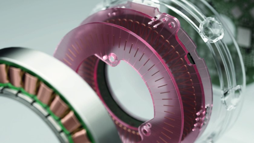
A direct-drive frameless motor kit includes a stator and rotor, without a housing or other mechanicals such as bearings and strain-wave gears. The stator consists of an iron stack, which provides rigidity and an end to the magnetic circuit, a copper winding (3-phase AC in case of our Omni Series of motors), and can also include optional features such as Hall-effect and temperature sensors. The rotor includes an even number of permanent magnets, alternating polarity, and typically includes a backiron – completing the magnetic circuit. Click for more information on our direct-drive frameless motor kits.
The stack length of a frameless motor refers to the length of the lamination stack that provides rigidity to the stator. The stack is built up of several individual laminations which help to reduce eddy currents. In slotted motors like those in the Omni Series, the stack includes the iron teeth around which copper wire is wound. The stack length does not include the winding end-turn lengths which are non-torque producing. Click for more information on our Omni Series of direct-drive frameless motors.
To convert between units of A_DC and A_peak of sine, use the equation below. A_peak of sine = 1.15 * A_DC Click here for more motor unit conversions.
Commutation is the method used to direct current through the phases of a three-phase motor. There are two types of commutation – trapezoidal (six state) or sinusoidal.
Trapezoidal Commutation: current flows through only two phases at a time and is directed based on Hall sensor feedback.
Sinusoidal Commutation: all three phases must be sinusoidally synchronized by the drive to provide a constant torque. Current is directed through all three phases using the position feedback from an encoder.
For more information, read the ‘Trapezoidal vs Sinusoidal Commutation‘ technical article.
Motor constant (Km) is equal to torque divided by the square-root of resistive power losses. It helps to show the efficiency of the motor (example: a higher motor constant means higher efficiency). The required motor constant for your application can be calculated and used to select a motor where there are significant thermal limitations, in which case the torque specifications on the datasheet may not be sufficient when rated at the limited temperature.
Click to read the technical article ‘Why Motor Constant Matters in Thermally Limited Applications’, for more information on motor constant and why it is useful for selecting a motor.
Low cogging torque or zero cogging torque motors provide smooth motion at low speeds. If you have a high cogging motor >3% of overall torque, the torque ripple caused by cogging torque at low speed will be much more noticeable. Our Agility Series motors are slotless and therefore offer zero-cogging torque. If you need a motor with higher overall torque but will still be operating at low speeds, our Omni Series motors offer low cogging torque while providing high torque density in a compact form factor.
To find out more about cogging torque please view our FAQ . Click for more information on Agility motors and Omni motors .General Technology
Key factors you may want to consider when choosing what linear position sensor you want to purchase include, the required measurement range, measurement accuracy, response time, and environmental conditions. For further information, read our guide on choosing the right sensor.
Novanta is not just an encoder company; we have the complete motion stack; servo drives, motors, and complete encoder systems! We offer scales and hubs with Aura P for standard and custom sizes. To further improve your manufacturing productivity, scales can be pre-mounted on hubs, so they’re ready for integration out of the box. Please consult the Ordering Information section of the datasheet for our offerings, and we encourage you to contact Celera Motion Technical Support for custom requests.
Yes, it is possible to mount the rotor to a metal housing with a plastic buffer. The buffer would need to be at least 3 mm thick to ensure the metal is sufficiently far away from the rotor so as to not adversely impact the sensor performance. An example would be to use a machined plastic shim or 3mm nylon spacers.
Please contact our Applications Engineering team for more guidance.
Initial Clarifications
The article you are about to read only applies to Summit products (Everest, Capitan & Denali).Requirements
This article assumes that the shunt braking resistor in your system has been properly dimensioned from your side. If that is not the case, please refer to the following link in order to get a calculation of the exact shunt resistor that your axis will require: Dimensioning a Shunt Resistor for Regenerative Braking .Taking care of the wiring and external circuitry
First of all, it is important to clarify that Summit servo drives do not have a shunt regulator transistor so it is always required to have an external circuitry handling the activation and deactivation of the shunt.Everest/Capitan/Denali XCR servo drives
For the XCR drives, you can find details on how to wire the external circuitry to the drive in the following links and the screenshot below:- https://drives.novantamotion.com/eve-xcr/power-supply-and-motor-power (Shunt Braking Resistor Connection section)

- https://drives.novantamotion.com/cap-xcr/power-supply-and-motor-power (Shunt Braking Resistor Connection section)
Everest/Capitan/Denali NET servo drives
For the NET drives, you can check the application guide on how to design this shunt circuitry on your PCB board:- https://drives.novantamotion.com/eve-net/schematic-design
- https://drives.novantamotion.com/eve-core/schematic-design
Everest/Capitan/Denali CORE servo drives
For the NET drives, you can check the application guide on how to design this shunt circuitry on your PCB board:- https://drives.novantamotion.com/cap-net/schematic-design
- https://drives.novantamotion.com/cap-core/schematic-design
Configuration of the shunt resistor in the drive
Once the above is taken care of, there is a very small set of registers that need to be configured in order to be able to trigger the activation of the external shunt resistors. These registers are:- SPI/Ethernet registers
- 0x122 – External shunt enable voltage
- 0x123 – External shunt disable voltage
- 0x5FC – Map output 1 (in case you want to activate the shunt resistor using GPO1)
- 0x5FD – Map output 2 (in case you want to activate the shunt resistor using GPO2)
- 0x5FE – Map output 3 (in case you want to activate the shunt resistor using GPO3)
- 0x5FF – Map output 4 (in case you want to activate the shunt resistor using GPO4)
- CANopen/EtherCAT registers
- 0x2122 – External shunt enable voltage
- 0x2123 – External shunt disable voltage
- 0x25FC – Map output 1 (in case you want to activate the shunt resistor using GPO1)
- 0x25FD – Map output 2 (in case you want to activate the shunt resistor using GPO2)
- 0x25FE – Map output 3 (in case you want to activate the shunt resistor using GPO3)
- 0x25FF – Map output 4 (in case you want to activate the shunt resistor using GPO4)
Initial Clarifications
The article you are about to read only applies to Summit products (Everest, Capitan & Denali).Steps
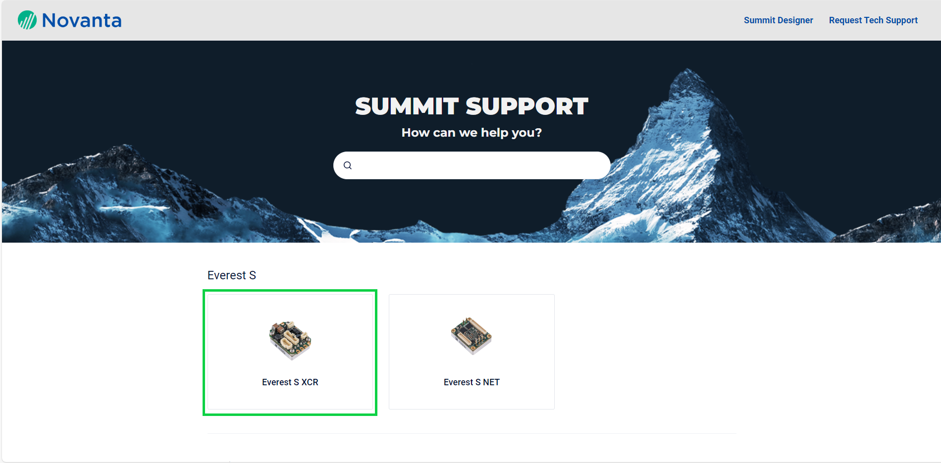
You can check the current firmware version of your drive by connecting to it and opening the drive explorer or the drive overview page (of the Wizard ):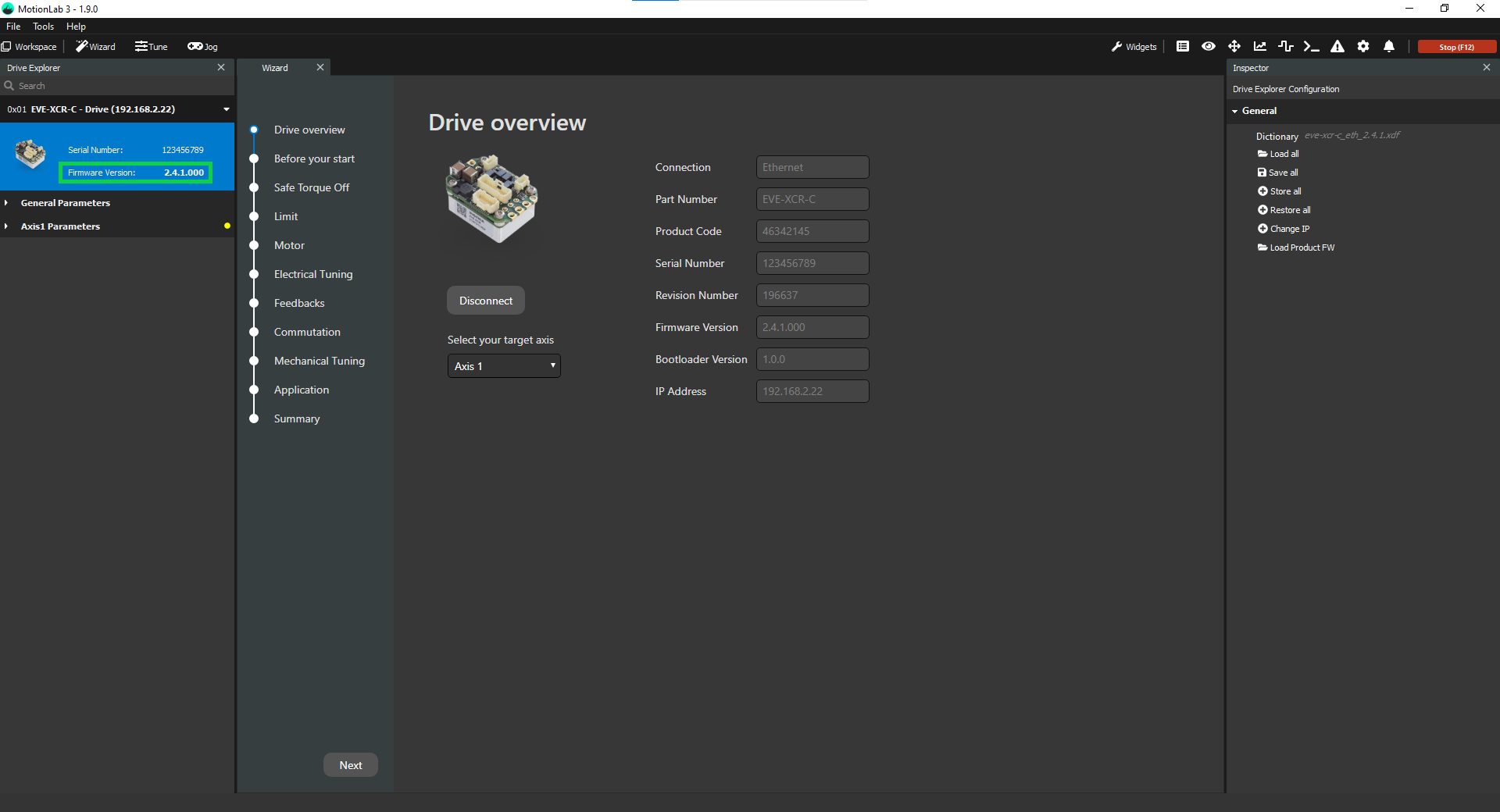 In order to find the latest version of the firmware for your drive, follow these steps:
- Navigate to our Support page.
- Select your drive (as an example, we will select Everest S XCR):
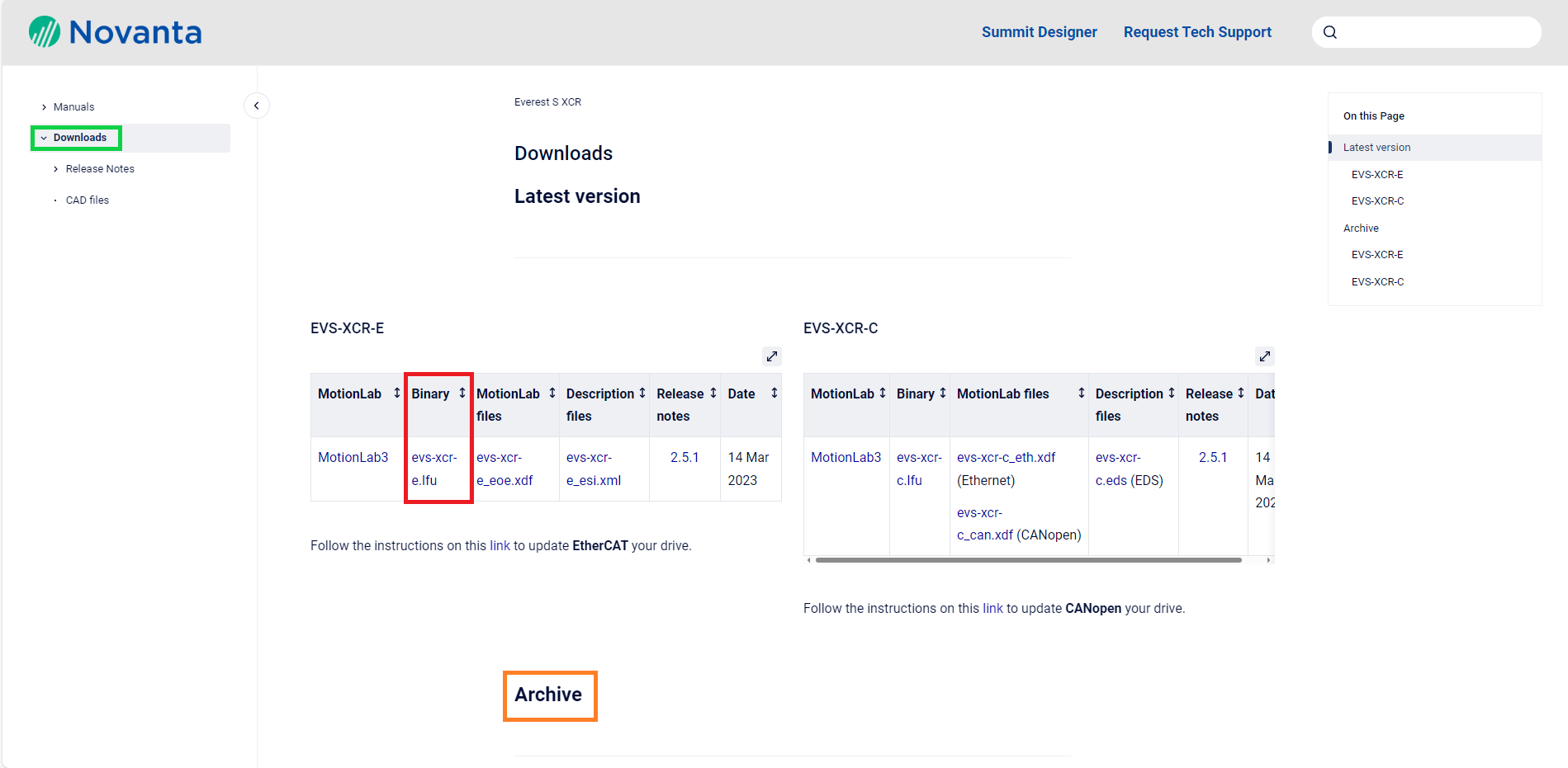
- Click on Downloads:

- Click on the binary file corresponding to your specific drive (older firmware versions are available in the “Archive” section):
To bond Soda Lime Glass to Titanium Grade 5, first clean the titanium surface with acetone. Next, abrade the adhesive surface-contacting surfaces with sandpaper to ~63 uin average or rougher surface finish then clean the surfaces thoroughly with Acetone. Primers are not required. While heat curing alone is sufficient, other curing options for Loctite AA 352 include UV light and heat or UV light and activator. Click here for more information on Glass Scales.
Absolute position feedback provides an absolute position to the controller at any point in time. If the system power cycles, no “wake and wiggle” is required to determine the position of the scale relative to the readhead. This is due to the sensor algorithm in the read head, paired with an absolute-type scale, such as a scale with an absolute barcode paired with an incremental track.
Legacy product documents can be found on our website here: https://www.celeramotion.com/resources/legacy-products/ Here you will find downloadable datasheets, interface drawings, installation manuals, and CAD files for our legacy products.
Incremental encoders measure the change and direction of motion. Absolute encoders provide absolute position feedback at any point in time. Incremental encoders need to go through a homing routine at start-up to locate the index, which is a zero position or “home”. The main track of the incremental encoder is detected to measure high resolution change in position. Absolute encoders do not need to go through a homing routine at startup, because a unique signal is detected at each location. Since absolute encoders require more complex sensor technology, it has higher latency than the incremental encoder that has zero latency. For more information on our absolute encoders, view our Aura Series absolute encoders, and Zettlex inductive encoders. Read more about Incremental Encoders vs Absolute Encoders here. Click for more information on our incremental encoders.
Kit encoders generally include a read head and measurement scale, or coded track. Fully packaged encoders, such as shaft rotary encoders, include the readhead and scale contained in a housing assembled around a bearing. Kit encoders typically have a much more compact form-factor and can be lower in weight and price, due to fewer mechanical components. Alignment of a kit encoder is crucial to achieving the specified performance. Fully packaged encoders on the other hand, offer a fast installation time at the cost of a larger and heavier form-factor. Learn more about our kit encoders.
IncOder Specific
SSI, BiSS-C, SPI and ASI (Asynchronous Serial Outputs). A complete list of protocol options can be found in the datasheet.
IncOder CORE can be purchased by specifying your sensor part number with CORE-X-XXX… on your Purchase Order. IncOder CORE can be purchased through our online configurator here.
The IncOder CORE feedback sensor should be considered where the need for an inductive encoder solution with significantly reduced weight is important, particularly in low inertia, low energy applications e.g. camera gimbals, robotic joints, and rotary actuators. Additionally, IncOder CORE is more economically priced compared with IncOder, for medical and industrial OEM solutions focussed on scalability. IncOder CORE is suited for motion systems do not necessarily require the extreme environmental performance of IncOder however want to take advantage of its high reliability and robustness, immunity to dust and dirt, high resolution measurement output and easy-to-install capabilities.
Multiturn IncOder provides single turn resolutions of:
- up to 21 bits for sizes 150 – 300mm OD,
- up to 20 bits for sizes 75 – 125mm OD.
- 12 bits (0 – 4095 counts) for BIS31, SPI31, ASI31 and ASI32,
- 8 bits (0 – 255 counts) for SSI options.
features the same robust sensing technology, electronic design and software components as
, but in a significantly lighter package. By designing the stator and rotor PCB structures to the appropriate thicknesses, and integrating mounting features into the board itself, the sensor board becomes self-supporting enabling a significant decrease in sensor weight compared to the housed IncOder variant. The cost of the sensor is also appreciably smaller than IncOder. IncOder offers a gear change in environmental robustness due to its housed and potted design: broader operating temperatures, high shock and vibration performance, shielding, operation in wet environments.
Yes – the Zero Point can be changed using the Zero Set and Zero Reset lines on the electrical interface. The Zero Set signal will set the current IncOder position as the Zero Point (held in memory when power is removed). Zero-Reset signal will reset the Zero Point to the factory setting (held in memory when power is removed). To use, the relevant connection should be connected to an electrical ground (<0.5 V) for at least 3 seconds at power-up but left unconnected (i.e. open circuit) during operation.
The maximum speed for any IncOder type is specified in the Product guide and is dependent on the size of the IncOder, as well as the communication protocol type. It is the maximum speed at which position measurement will be taken. The fastest physical speed is specified as 10,000 rpm. In some cases, such as for Mini IncOders and Mini Ultra IncOders it may be possible to measure position at a faster angular speed than specified. Please contact Celera Motion for more information.
No. If the IncOder were to move whilst the power is off, then when power is re-applied the IncOder cannot determine how many revolutions may have been performed. It is a requirement that the IncOder does not move by more than ±1.5 degrees whilst power is off. Multiturn IncOder is an absolute inductive encoder with non-volatile turn count storage. Turn count is stored in this non-volatile memory so that it is retained during “loss of power” events. When power is re-established, the turn count is retrieved and turn counting will continue. See our Multiturn IncOder page for more information.
Multiturn IncOders can be selected by choosing one of the protocols: SSI31, SSI32, BIS31, SPI31 ASI31 or ASI32.
By default, IncOder only outputs Single Turn position data, being angle position data over 1 rotation (360 degrees). Multiturn encoders have the ability to count Multiturn data (the number of complete rotations of the sensor). Multiturn IncOder options are available for our Midi IncOder series by specifying the following protocol production options: SSI31, SSI32, SPI31, ASI31, ASI32 or BIS32. SSI based options provide 8 bits of turn count (0-255). BiSS, SPI and ASI options provide 12 bits of turn count (0-4095). Conventional multiturn devices are able to increment Turn Count data when the device isn’t powered, which is not the case for Multiturn IncOder where Turn Count data doesn’t change when the device isn’t powered. When power to Multiturn IncOder devices is removed, this event will be detected and position information is stored in non-volatile memory. Once the device is powered again, this data is recovered. Note that if the Midi IncOder moves >1.5 degrees, an error condition will persist. The Midi IncOder will continue to indicate this error until the error is reset. Further details of this process can be found in our product guides. Configure a Midi IncOder Configure a Midi Ultra IncOder Read more about Multiturn IncOder here.
Light Industrial Precision Machining
Yes, the M321/M328 spindle is specifically designed to have replaceable collets without the need to rebalance the shaft. Click for more information on the Light Industrial Series spindles.
Various collet sizes are available for the M321/M328, from 3mm, 1/8″, 4mm to a maximum of 6mm shank diameter, both for the manual and automatic collet versions. Additional specifications.
For normal machining applications, the minimum recommended speed for the M321 and M328 Light Industrial Series spindles are 10,000 rpm, although for soft materials such as perspex, lower speeds may be possible. More information on the Light Industrial Series spindles.
Both the M321 and the M328 need to be watercooled and connected to an external chiller, due to the high speed of operation and the powerful integrated motor. The D1091 is an air cooled spindle, and does not require water cooling. Click for more information on the Light Industrial Series spindles.
PCB Drilling and Routing
Most of our modern PCB Drilling & Routing spindles are fitted with a bonded collet, which cannot be removed by the customer. In this case, the spindle should be sent to Celera Motion’s Westwind authorized repair center to have a new collet fitted. However, some products are still fitted with a removable collet, and in this case, the customer should contact the closest Air Bearing Spindles Center of Excellence found in the Contact section of our website, to discuss which part to order.
Supply pressure for the cooling water of a PCB Drilling & Routing Series spindle should be 3 to 4 bar (43.5 – 58 psi). Specifications for the PCB Drilling & Routing Series can be found here.
Air pressure used for a PCB Drilling & Routing Series spindle should be 5 to 6 bar (72.5 to 87 psi). More information on the PCB Drilling & Routing Series.
Please refer to your machine manufacturer’s recommendations. Currently 6.35mm is the maximum we recommend for most Westwind PCB Spindles.
Product Specific
The Aura P utilizes optical reflective technology to read position. This platform tends to be more susceptible to contamination, so having clean optics is vital to encoder function. After installation, please follow the cleaning procedure outlined here.
Scale eccentricity and bearing runout have dramatic effects on accuracy. For example, an eccentricity of 0.1mm will result in a significant angular error of 0.44°. Minimizing eccentricity can be difficult; the scale alignment process is time-consuming, and averaging out the error with two readheads may not be possible where space and resources are limited. That’s why we made Aura P with built-in eccentricity compensation that can be performed within our SmartPrecision III software.
Yes, you can cut Aura P glass scales to shorter lengths. However, when doing so, you have to take some precautions. On both ends of the scale is a buffer zone. These zones limit the Aura P from optically traveling off of the grating patterns. If the buffer zones are altered by shortening the scale, Aura P may report an incorrect position at either end of the scale. Therefore, before making any cuts, ensure that there is an adequate measuring distance that includes buffer zones on both ends of the axis of motion. The mechanical alignment can be referenced in the Installation section of the datasheet. The encoder optics should always be at least 2.4576 mm from the scale edge. This value accounts for 0.02 mm of potential glass edge chips and defects resulting from the cutting process.
If you haven’t already, please download and read through the Aura P datasheet, which can be found here. This document holds all of the necessary information for Aura P storage, handling, installation, and calibration. If you have any product questions or questions pertaining to your specific project, please contact Celera Motion Technical Support. After submitting a request, you’ll be paired with a knowledgeable member of our Application Engineering team who’s ready to assist.
Thank you for your interest in our product! Please click here to be directed to our quote request portal. Submitting a request will take less than a minute and will put you directly in contact with a helpful member of our Sales team. We’re looking forward to working with you!
If you’re looking for more information on Aura P, please click here to be directed to the product page. There, you’ll find downloads for the datasheet, brochure, interface drawings, SmartPrecision III (Aura Series’ calibration software), and CAD files available in a host of formats. If you require any additional information not covered in our documentation, please reach out to Celera Motion Technical Support.
With the Aura P, it’s now faster and easier than ever to install and integrate an Aura encoder into your motion system. This PCBA format will accelerate your time to market, and allow you the flexibility to transition to the same encoder in an SMT package as you scale.
Aura P is the newest addition to Celera Motion’s Aura Series. While previously only available in an SMT format, Aura, our smallest high-resolution absolute encoder, is now offered in a PCBA package.
The Absolute MDrive has the same encoder resolution as the existing closed-loop Liberty MDrive products, 1000 lines or 4000 counts/revolution.
Aura absolute encoders, when paired with rotary glass scales can achieve accuracy between /- 0.005-0.01 degrees depending on scale size and assuming both misalignment and eccentricity calibrations have been performed. Linear encoder accuracy also varies based on scale size. For an 80mm glass scale length, Aura can achieve /- 2um accuracy. For more information on our Aura absolute optical encoders, please visit the Aura product page.
Rotary Atomizer Spindles
Yes, lightweight materials are used in rotary atomizer spindles. Many of our atomizers are designed to be fitted to robotic arms or linear movers, therefore the atomizer weight is extremely important. Click here for additional information on coating atomizer spindles.
Most of our atomizers are designed to be fitted with some form of external speed sensor to monitor shaft speed. These sensors can be activated optically, by black/white stripes on the turbine wheel, or magnetically, by magnets embedded in the side of the turbine wheel. It is the responsibility of the OEM to supply and fit the appropriate sensors and circuitry. Click here for additional information on our coating atomizer spindles.
All of Celera Motion’s Westwind atomizers are designed to operate without the need for water cooling. These coating atomizers rely on turbine exhaust air and paint flow through the shaft to remove any heat generated within the bearing assembly. Click for more information on our coating atomizer spindles.
Talk to an Expert
Ready to overcome your challenges and unlock the full potential of your robotic applications? Contact our expert team today.